
3D inspection
Capture surface geometry for dimensional review and comparison against available CAD data.
Start typing to find a product, material, application or SKU.
No matching products found. Try a different term or category.
 Silicone RubberElastomer and Plastic Products · Rubber Cords and SheetsView
  FKM-O-RINGO-Ring · Sealing SolutionsView
  Polyurethane O-RingOil Seal · Sealing SolutionsView
  Oil seal FKMOil Seal · Sealing SolutionsView
  Small PU transparent Flap Valve Fits SandPiper Pumps338-010-357View
  Big PU transparent Flap Valve Fits SandPiper Pumps338-011-357View
 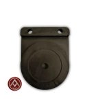 Small black NBR Flap Valve Fits SandPiper Pumps338-005-360View
 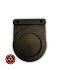 Big black NBR Flap valve Fits SandPiper Pumps338-008-360View
 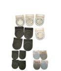 V338-008-365 Flap, Check (ST Steel/Neoprene) Fits SandPiper PumpsView
 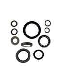 Bonded SealSealing SolutionsView
 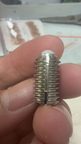 Custom SS304 Ball Plunger ScrewPrecision Metal ComponentsView
 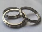 KF Centering RingVacuum Seals & Centering RingsView
  Customised Size High Performance PlasticElastomer and Plastic ProductsView
  Customised Size ElastomerElastomer and Plastic ProductsView
 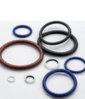 Encapsulated O-RingO-RingView
 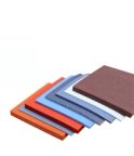 Silicone Sponge RubberSilicone ComponentsView
 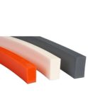 Silicone Solid RubberSilicone ComponentsView
 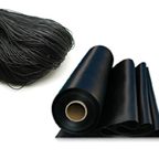 Rubber SheetRubber Cords and SheetsView
  Rubber CordRubber Cords and SheetsView
  PTFE Gland PackingPTFE Gland Packing · Sealing SolutionsView
  GasketGasketView
  KF Outer Support RingVacuum Seals & Centering RingsView
 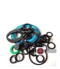 Rod SealHydraulic SealsView
  Vari SealOil SealView
 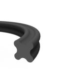 X-RingO-RingView
 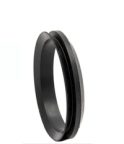 V-RingO-RingView
  Teflon PTFE O-RingO-RingView
 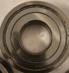 Barden VCMP209ASP Vacuum Pump BearingVCMP209ASPView
 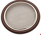 KF Centering Ring with MeshVacuum Seals & Centering RingsView
 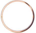 CF Copper GasketVacuum Seals & Centering RingsView
 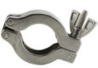 KF Vacuum ClampVacuum Clamps & SupportsView
  MOLYKOTE® D-321 R Anti-Friction Coating SprayD-321 RView
 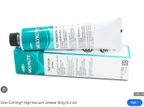 MOLYKOTE® High Vacuum GreaseIndustrial Lubricants & CoatingsView
  Vacuum Clamp Type 3Vacuum Clamps & SupportsView
  Vacuum Clamp Type 4Vacuum Clamps & SupportsView
  Single-Pin Vacuum ClampVacuum Clamps & SupportsView
 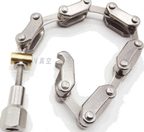 KF Chain ClampVacuum Clamps & SupportsView
 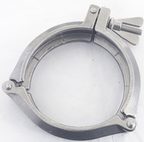 KF Three-Piece ClampVacuum Clamps & SupportsView
  Bulkhead Clamp Type 1Vacuum Clamps & SupportsView
  Bulkhead Clamp Type 2Vacuum Clamps & SupportsView
 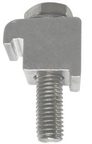 ISO Double-Claw ClampVacuum Clamps & SupportsView
 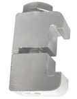 ISO Single-Claw ClampVacuum Clamps & SupportsView
 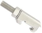 ISO Hook BoltVacuum Clamps & SupportsView
 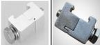 ISO Claw Clamp M10Vacuum Clamps & SupportsView
 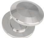 KF Blank FlangeVacuum Flanges & FittingsView
  KF ElbowVacuum Flanges & FittingsView
  KF TeeVacuum Flanges & FittingsView
  KF CrossVacuum Flanges & FittingsView
 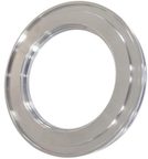 ISO Vacuum FlangeVacuum Flanges & FittingsView
 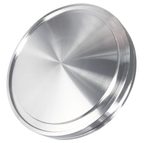 ISO Blank FlangeVacuum Flanges & FittingsView
 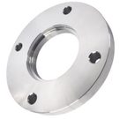 ISO Fixed FlangeVacuum Flanges & FittingsView
 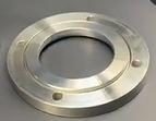 ISO Socket FlangeVacuum Flanges & FittingsView
 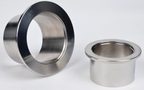 KF Weld-Stub FlangeVacuum Flanges & FittingsView
 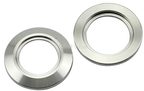 KF Weld Socket RingVacuum Flanges & FittingsView
 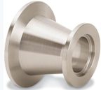 KF ReducerVacuum Flanges & FittingsView
 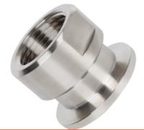 KF CouplingVacuum Flanges & FittingsView
 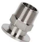 KF Hex NippleVacuum Flanges & FittingsView
 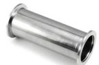 KF Straight PipeVacuum Flanges & FittingsView
 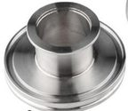 ISO-to-KF ReducerVacuum Flanges & FittingsView
 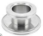 ISO ReducerVacuum Flanges & FittingsView
  ISO ElbowVacuum Flanges & FittingsView
 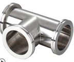 ISO TeeVacuum Flanges & FittingsView
 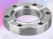 CF Weld FlangeVacuum Flanges & FittingsView
 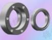 CF Socket FlangeVacuum Flanges & FittingsView
 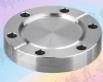 CF Blank FlangeVacuum Flanges & FittingsView
  CF ElbowVacuum Flanges & FittingsView
  CF TeeVacuum Flanges & FittingsView
  CF CrossVacuum Flanges & FittingsView
 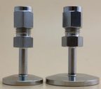 VCR-Type Face-Seal AdapterVacuum Hoses & AdaptersView
 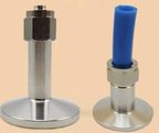 KF Hose-Barb LockVacuum Hoses & AdaptersView
 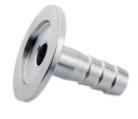 KF Hose BarbVacuum Hoses & AdaptersView
 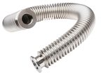 KF Flexible HoseVacuum Hoses & AdaptersView
 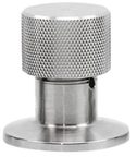 KF Exhaust ValveVacuum ValvesView
 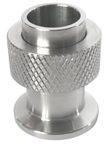 KF Gauge Seat ValveVacuum ValvesView
 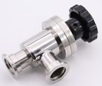 KF Angle-Seat ValveVacuum ValvesView
 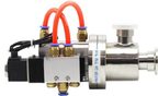 Pneumatic KF Angle-Seat ValveVacuum ValvesView
 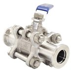 KF Ball ValveVacuum ValvesView
 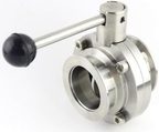 KF Butterfly ValveVacuum ValvesView
 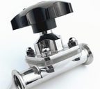 KF Diaphragm ValveVacuum ValvesView
 Industrial measurement services
Capture complex geometry, inspect deviations and create reliable digital data for reverse engineering, product development and 3D printing workflows.
 Industrial capture · Digital geometry
Where it helps
Capture surface geometry for dimensional review and comparison against available CAD data.
Digitise existing components to support replacement, redesign and design improvement.
Obtain accurate reference geometry to speed design iteration and optimisation.
Create digital geometry for prototyping and additive manufacturing workflows.
Inspection workflow
The physical component is captured from accessible angles, processed into digital geometry and reviewed against the available drawing or CAD reference.
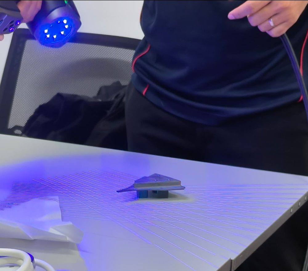
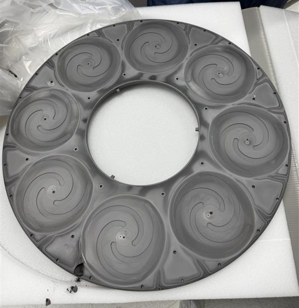
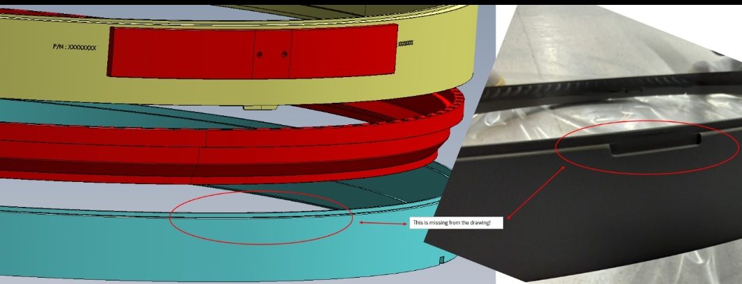
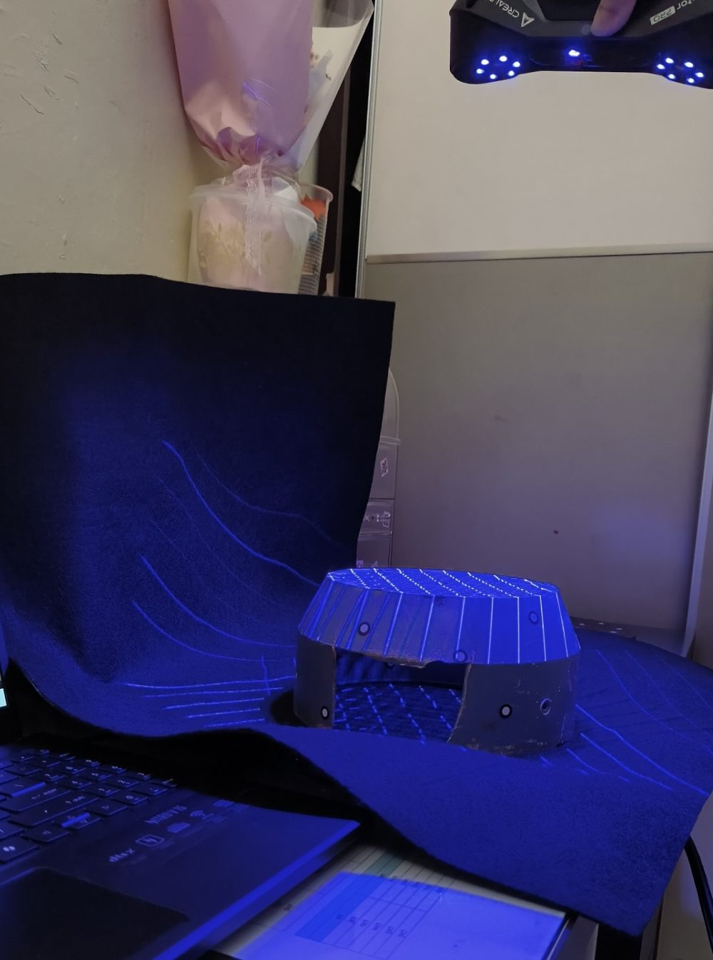
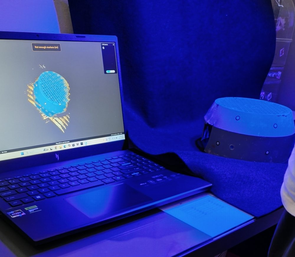
Reverse-engineering case study
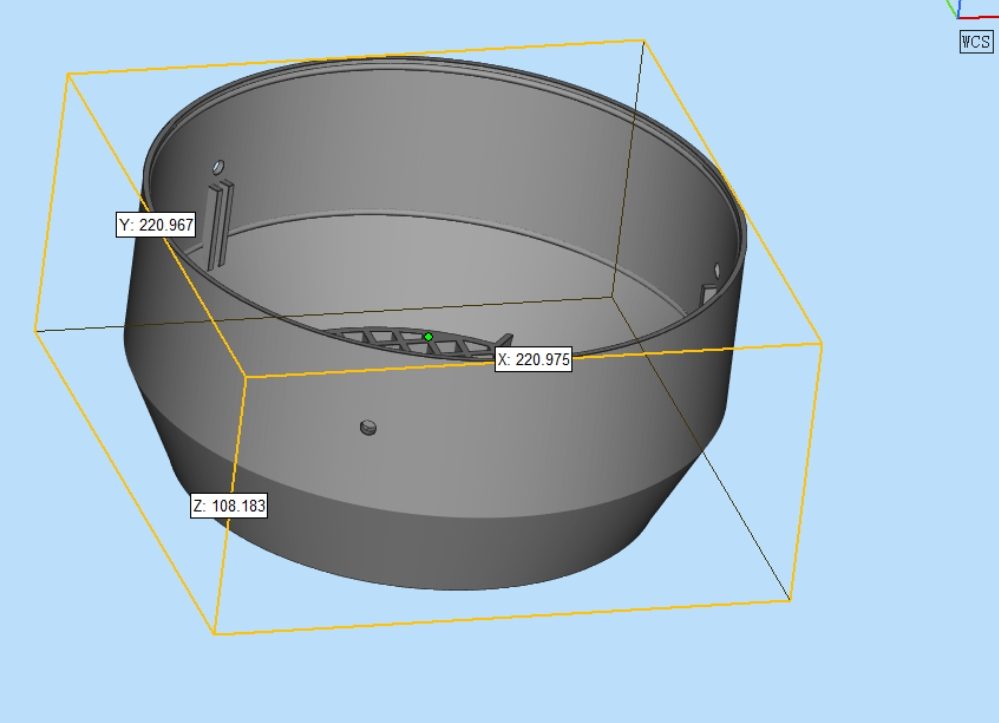
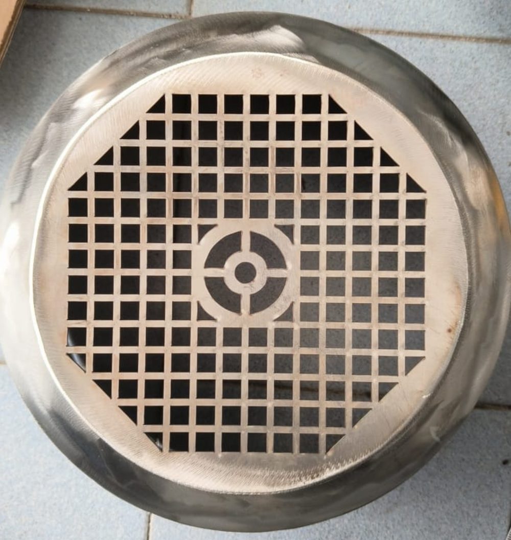
This motor-cover project shows the progression from marker-assisted capture and live scan review to reconstructed CAD geometry and the finished stainless-steel component.
Typical outputs
Processed scan data suitable for review and downstream engineering work.
Comparison against available CAD data to identify dimensional differences.
Geometry that supports part recreation, redesign and improvement.
Digital input for prototyping and 3D printing workflows.
How it works
Tell us what needs to be captured, checked, recreated or developed.
The component is prepared and its accessible geometry is digitally captured.
Scan data is cleaned, aligned and reviewed around the required application.
You receive the agreed digital output for inspection or engineering use.
More scanning applications
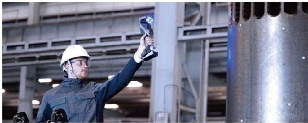
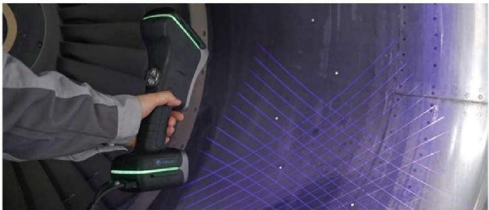
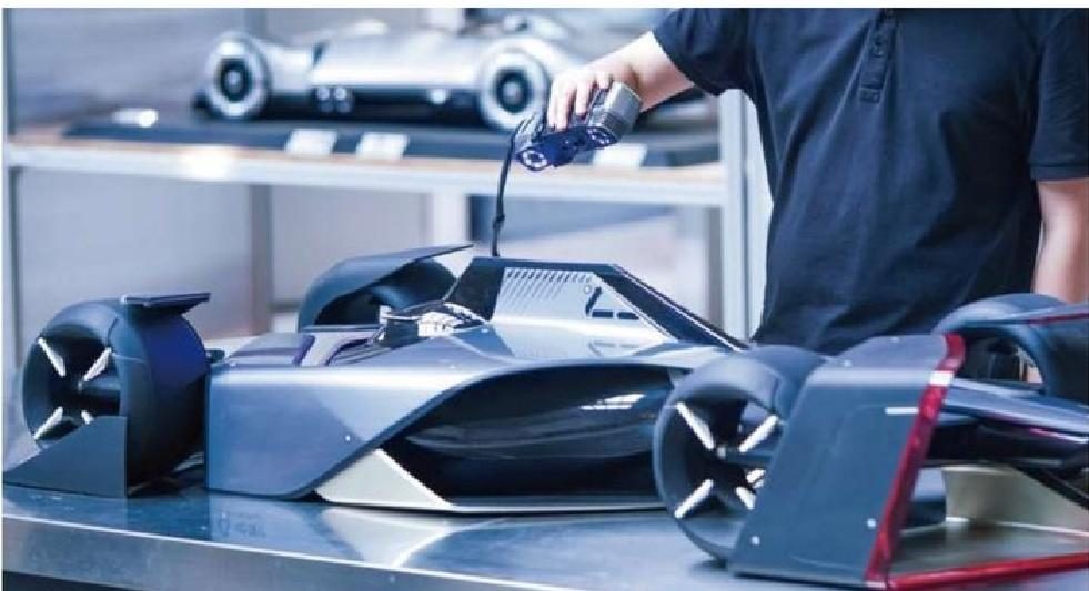
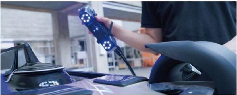
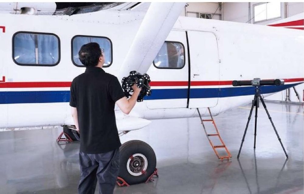
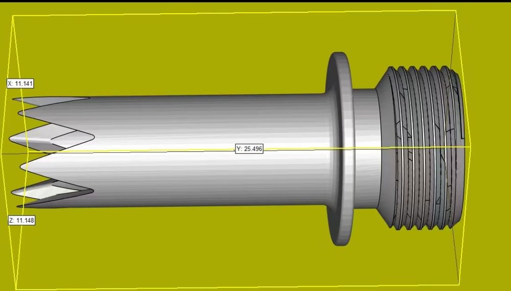
Browse examples spanning large industrial surfaces, vehicle and aircraft models, and custom components recreated from measured geometry.
Start with the application
Share the component, application and required outcome. AKVT will review the scanning approach and next steps.